
The Linear Electro-Optic Effect
First described in 1906 by F. Pockels, the linear electro-optic effect occurs in crystals which lack a center of symmetry and is observed as a change in refractive index produced by an applied electric field. The change is small, but is sufficient to alter the spatial phase condition of light.
To make use of this effect, light must propagate through the crystal normal to a direction in which the refractive index change can be produced. If the incident polarization direction is at 45° to the principle refractive index values, then the light will exit the crystal as two orthogonal components with a phase difference between the ordinary and the extra-ordinary ray which is linearly proportional to the applied electric field. These components combine in space to form generally elliptical polarization states (linear and circular polarization being special forms of elliptical polarization).
The Pockels cell designer must choose an appropriate material which produces a large induced birefringence and then maximize its effect by a sensible choice of crystal cut, light path and applied electric field directions. When the electric field is applied along the light path then the modulator is referred to as longitudinal and if the field is across the light path, then the modulator is transverse.
The most frequently used materials for longitudinal mode Pockels cells are KDP and more commonly, the deuterated form KD*P. This has a modest half wave voltage (the voltage which must be applied to produce a pi radian phase shift, equal to a polarization rotation of 90°) of around 6kV at 1064nm and has extremely high resistance to laser damage as well as being available in excellent quality crystals of large sizes. For these reasons, all our longitudinal mode Pockels cells are manufactured from >95% deuterated KD*P.
Selecting the Optimum Pockels Cell for Q-Switching
For Q-Switching applications, the device must be able to withstand extremely high intra-cavity optical power densities. These are usually many times higher than those indicated by the peak output power which is measured outside the cavity because the circulating optical field is enhanced by the cavity Q. In many cases, only those devices based on KD*P will withstand such high intensities, although lithium niobate has been shown to be effective in moderately high power applications around 1μm wavelength.
Next is the choice of longitudinal or transverse field device. This is often dictated by the required aperture of the Pockels cell. Large apertures are more easily obtained in longitudinal devices as the half wave voltage is effectively independent of crystal dimensions. For a transverse field device, the half wave voltage is determined by amongst other things, the ratio of length to aperture (higher being more favorable). The apparent benefits of lower switching voltage are however often outweighed by other factors. In particular, most of the transverse field devices require multiple crystal designs to counter effects of birefringence and sometimes walk-off as well which occur in devices where the beam does not propagate along the optic axis. For most applications, longitudinal cells offer the simplest solution and are thus often preferred.
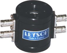
Another consideration is safety. Will the Pockels cell be in an exposed position where the user may have access to the device? If so, then great care must be exercised in the choice of interconnect used on the cell. For exposed positions we recommend the use of the EM5XX range where high voltage BNC type connectors are employed. For those units which are embedded within an enclosed section of the laser system, or where other engineering safety controls are in place, a more open style of interconnect may be used such as the simple or stud pin terminals used on the EM508M and EM510M devices (see left). This also allows a more compact packaging and can additionally present lower capacitance to the Pockels cell driver.
Setting up the Q-switch
For the purposes of this discussion, we shall assume that the Q-switch is of the longitudinal KD*P variety as this is the most common form of Pockels cell used for Q-switching. We would recommend that the user familiarizes themselves with the characteristics of the cell at a visible wavelength before attempting to set up for IR sources such as Nd:YAG. This will make it easier to understand what is happening when you adjust the cell in the final laser set-up.
The rotation of the Pockels cell in its mount should be adjusted such that the input laser polarization axis is aligned with the axis of the connectors. This is the standard alignment for all Leysop longitudinal Pockels cells. The analyzing polarizer should be set orthogonal to the input polarizer such that in the absence of the Pockels cell a clean extinction of the beam occurs. Place the Pockels cell in its position between the polarizers and arrange for the input beam to spread to fill the input aperture of the cell. This is easily achieved using a ground glass diffuser or even a piece of sticky tape a moderate distance from the input window. Now observe the scattered light which is transmitted onto a screen some distance after the analyzing polarizer.

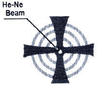
The image on the screen should look something like that on the left. This is known as the isogyre pattern and is caused by interference of the divergent light at angles corresponding to directions at which an additional wavelength of path difference has been added by the birefringence of the crystal. They are effectively fringes of equal birefringence. When the pattern is centered with a good extinction of the HeNe beam (although some breakthrough of the beam is usually visible), the cell is axially aligned. If the pattern is off centre, the cell must be adjusted in altitude and azimuth until the pattern is centered. Please note that the pattern is not affected by displacements of the beam centre, only the angle of propagation through the cell.
It is helpful in setting up infrared lasers if this procedure can be followed using a low power HeNe laser which has been aligned to the axis of the laser optics. Often a retro-reflection off the laser rod can be used to set up the HeNe. Obviously, in all these discussions it is assumed that the user will observe the usual laser safety precautions to protect themselves and others present.
This process will have aligned the Pockels cell to the optical axis of the laser and orientated the cell to align the polarization axis to the crystal axis of the Q-switch crystal, the diffuser may now be removed. The next task is to adjust the voltage applied by the Q-switch driver to produce the correct degree of phase retardation to give a 90° polarization rotation (assuming half-wave and not quarter wave switching is to be employed, but that’s to be the subject of another application note). This must usually be done dynamically as the voltage which produces the necessary rotation when applied under dc conditions, is lower than the dynamic voltage requirement by about 20%. In all cases, the peak switching voltage should be incremented gradually whilst monitoring the performance of the laser produced. If the device is set up for “on Q-switching” the laser should be held off by the polarization selectivity of the cavity components and the increasing of the switching voltage will increase the laser output until the peak output is obtained. For “off Q-switching”, the laser is held off by the rotation of the polarization by the Pockels cell. In this case, the full half wave voltage may not always be required and it is recommended that the d.c. hold off voltage is increased until hold off is achieved at full optical pump power (with a little margin in hand). Any further increases will not reap any benefits and will just shorten the life of the Q-switch crystal (which will break down under long term application of high d.c. voltage).